Tuesday, April 7, 2020

Engine Arrival

The single most expensive part of this build is the engine and gearbox. For my cobra, I have gone with a new LS3 and Tremec TKO 600 gearbox from Roadcraft. These guys come highly recommend by AK and after speaking to Bob (from Roadcraft) it easy to see why. There are very professional and happy to answer all my silly questions. Due to their strong working relationship with AK, they understand the engine requirements. They change the oil pan for a shallower unit and the exhaust manifolds are swapped for a pair off a corvette. They also prime the engine oil system, fit ancillaries, clutch, and flywheel. The kit also includes a Tremec TKO600 which is shipped separately. The only engine component which was not included is the ECU and that will be a subject for another entry. I also chose to purchases these additional items to make my life easier
  • Gearbox Propshaft yoke
  • Alternator wiring plug
  • Mechanical Speedo hole blank kit
  • Speedo plug/harness
  • Reverse light plug/switch
Once you have made the decision and pressed the go button, there is then a two month lead time. Whilst this is an agonizing wait it does give you more time to finish the brake lines. 

As you might be able to tell from the photos in this blog the engine arrived late summer 2019, so I’m still a little behind with these posts. 

A Knock on the Door

One early morning there was a knock at the door with a delivery van parked outside. What was inside was the beating heart of my AK Cobra :D. The delivery man was jovial and quickly offloaded the 400 kg pallet and carefully maneuvered it and the pallet truck into my garage. 

Package!!
With the black protective film removed the collection of boxes become apparent. Clearly, the large bottom crate contains the engine, which makes the large top box the Tremec gearbox. The alternator and starter motor also seems to come in separate packages. The gearbox yoke is found safely packed away in the Tremec box along with some general instructions (I'll upload these later). Roadcraft have fitted the remainder gearbox speedo items. 

More packaging.
Having removed the smaller boxes and strapping, next was the gearbox. This was a little too heavy and too high to safely lift off the pallet. We, therefore, broke out the engine hoist and some strops to gently lift it down. 

Lifting the gearbox off the engine.
After some careful strapping and boy scout knots, the gearbox was easily lowered to the ground. Whilst my dad wound down the gearbox, due to the unbalanced load, I supported the far end of the box. 

Gearbox almost on the floor.
With the gearbox on the box on the floor, we had a sneak peek of what’s inside. The internal packing cardboard was amazingly sturdy. After admiring it for a few moments it then quickly slid to one side so the engine itself could be unpacked 

Inside Tremec box.
Now onto the main event, the engine. This was trapped in what appeared to be a cardboard box with wooden planks at each end. These were screwed through the cardboard into what turned out to be a wooden frame. With these screws and wooden planks easily removed, the cardboard box could be lifted up. 

Now to unpack the engine.
With the cardboard removed we can get our first glimpse of the engine, wow what a beast. It is however still secured within a wooden frame though so more screws to undo. 

A sneaky peak at the new engine.
The surrounding wooden frame is easily unbolted from the smaller of the wooden pallets and then lifted over the block. 

One last part to remove!
With the engine finally out and in the open, it does look amazing! The engine is loosely bolted to the wooden frame by a couple of metal straps. Whilst these are easy enough to remove, my plan, for now, is to use this frame as a makeshift engine stand so I will leave them in place. 

A first good look at my new engine.
The remaining issue is that the small wooden frame/engine stand is all resting on a much larger wooden pallet which was used for transportation. The larger pallet is taking up far too much floor space, and so needs to go. Given the approx. 200 kg of the engine this is not a simple as lifting it offhand or safely sliding off! Luckily I spotted this issue a few months back and purchased an engine hoist. 

Lifting the bloody thing

Whilst I do have an engine hoist and some strops, I have no idea where to lift the engine from. A good read of the numerous LS swap blogs and previous AK builders blogs, reveals multiple methods for lifting these engines. These ranged from wrapping old seat belts or strops around the block (ref) to using a bespoke metal plate which is bolted into the galley and used as a mounting point for chain/shackles to lift the engine. I didn’t fancy the first approach as you could crush the oil pan, due to the weight of the engine which is supporting above. The later seems to be the approved GM method, with pre-made brackets available from the states, if you want to wait for the shipping. You could fabricate your own custom plate, as this video shows, however, I would prefer to not unbolt too much of block for fear of damaging it before it even cranks over. A quick chat with Roadcraft and they suggested fitting bolts to the end faces of the cylinder heads and lifting from there with a load balancer. My concern with this approach is that you are then effectively lifting the engine from the 10 or so bolts which connect the head to the block. However, since this is what Roadcraft does on a regular basis, I will follow suit. 

This means the next tool to purchase is an engine leveler for my hoist. After a quick look on eBay, this one was soon in the post. Before its arrival, I thought it best to remove the air intake and any ancillaries from the engine to avoid them being damaged by the lifting chains. 

Before I could do this, I first needed to know what I could remove and how to do this. I found this great article online which walks you through the process of removing the air intake manifold from an in situ LS3. I won’t parrot all the steps here, but it’s a simple case of removing the stock throttle body, by removing the 4 Allen head bolts on its front face. 

Off comes the stock throttle body.

Whilst my dad was removing the throttle body, I started to remove the 12 x 10 mm bolts which secure the intake manifold to the heads. These are not expansion bolts and they are all the same length. However to keep things organized I fashioned a labeled bolt holder out of scrap cardboard. 

Throttle body removed,

Manifold bolts.
With the bolts removed next the step is to disconnect the evap pipe from the front of the intake manifold. Whilst removing this it is also prudent to also remove the solenoid (found at the other end of the evap pipe) and its bracket (15 mm bolt) which mounts to the front end face of the header on the driver side. This evap system is not required by the UK IVA test and so can be permanently removed. I will need to plug the open port in the manifold later. 

With that removed the intake manifold along with the fuel rail/injectors can be lifted off from the engine. Having the fuel railed mounted to the air intake is a neat solution. 

Lifting off the intake manifold.
With the manifold removed, the rectangular ports on the header are exposed. To keep dirt/dust out of the head/cylinders a quick cardboard cover is made and taped over the ports. The final part which I needed to remove from the engine is the power steering reservoir and bracket. This is mainly because I intend to use this bolt hole as a mounting location for the load balancer. The reservoir is removed, by loosening the jubilee clip securing the pipe and then slowly lifting the reservoir up and off of the pipe/bracket. The bracket then easily unbolts and the bolt is then placed in the end of the exposed pipe to avoid contaminates entering. 

Removed intake manifold.
With the engine stripped down sufficiently the load leveler can be bolted to the heads. This was done at four locations using M10 8.8 strength bolts (same as those used for the engine mount brackets). Despite having secured the load leveler to the engine, the next challenge is getting the jib on the engine hoist close enough. The problem here is that the base of the wooden pallet is wider than the legs of the hoist. The solution was to carefully cut sections out from the floor of the bottom pallet so I could slice the legs of the hoist underneath. 


Lifting the engine of the large pallet.

Small pallet resting on the legs of the hoist.
With the hoist finally over the top of the engine, the first engine lift was very straight forward and satisfying. This moment of joy as then brought down to earth as when I came to lower the smaller pallet to the ground, I had a similar problem with the width of the smaller pallet being wider and hoist legs (again!!!). The solution was again to cut sections out of the bottom braces. However, this time, that wasn’t the end of the story, as I then noticed that the height of the smaller pallet was a little lower than the height of the legs of the hoist e.g. the pallet sat of engine hoist legs when lowered down. A makeshift solution was to use the offcut pieces of wood from the pallets to rest the smaller pallet on. 

For now, the engine will leave in a corner of the garage out of the way, but as a constant source of motivation to finish the brake and clutch line install so I can get this beast sitting in the chassis. 

Temporary engine resting place.

Tuesday, February 18, 2020

Brake lines – part 2

In a previous post, I created the majority of the brake pipes, with the exception of the pipes around the brake servo. In this post, lets look at refurbishing a donor brake servo and master cylinder and creating a bracket for the end of the brake pipes.

Brake pipes taped to chassis.

Brake Servo

The AK 427 requires a Rover 25 (or Rover 200, MG ZR) brake servo and master cylinder. These are plentiful on eBay and go for around £25. After looking at the options I decided to purchase the item shown below, although it looked in better condition in the seller's photos. 

Donor brake servo – I swear it didn't look this bad in the seller's photos!
With a 13 mm socket, the two nuts which hold the servo on the master cylinder are removed. With these parts separated it is clear there is even more rust on the servo. It's like having flashbacks to the when I was cleaning/servicing the donor parts. 

Disassembled donor brake servo show signs of even more rust. 
As these two parts separate, be careful to keep track of a large O-ring, which seals the servo to the yellow collar on the master cylinder. With the nuts and O-rings stored away, both parts require a thorough sanding. After a morning of sanding the brake servo, it was starting to look a lot better and appears to have only been surface rust. 

Sanded down brake servo.
The rust was not limited to the servo and the brake cylinder also required a good sanding. 

Part sanded servo with masking tape.
Having finished the sanding, the prepped and keyed surfaces need a deep clean with plenty of white spirit. This included cleaning the white plastic reservoir on the servo to remove the old encrusted oil and some yellow writing. I had put this off until this point as I knew I would be making more mess with the sanding. To create a fresh protective base coat, I first gave these items a few coats of POR 15. 

Having left the POR15 dry, these parts were then given another light sanding, to create a keyed surface ready for a few thin coats of semi-gloss black topcoat. 

Parts awaiting a final top coat of gloss black paint. 
After leaving these parts to dry I was very happy with the final outcome. A marked improvement on the donor part which I started with. 

Freshly painted brake servo and master cylinder – looking much better. 
The final stage with this job is to resemble freshly painted parts. Before the actual assembly, it is worth checking the perishable parts on the servo, this includes two rubber boots which secure the reservoir to the servo and the previously mentioned O-ring. Both these parts can be found on Rimmer Bros and have the following part numbers. 
  • Front reservoir seal: EJP1502
  • Rear reservoir seal: EJP1503
  • ring: EJP1504
Upon initial inspection, these seem to be in perfect order and so at least for now, I will re-use the current parts. This might all change when I come to test the brakes, but we will see. 

Image highlighting rubber boot on brake servo.
To reduce the wear on the internals a small amount of bearing grease was added to the end of the servo. This refreshes the grease that was originally on this part as it was pulled apart. 

Bearing grease added 
And with that, the final step is to bolt the parts back together using the original nuts. Looking at it now and remembering how it originally looked I'm actually very impressed with my self. 

Re-assembled brake servo and master cylinder.

Time for a Bracket

As I mentioned in the first brake line post, I wanted to hard mount the end of the brake lines to the chassis. This hard mount point will then have brake Flexi running up to the brake servo, but that’s a challenge for another post. With Stu's excellent blog post as inspiration, I decided to fabricate my own metal bracket to secure the brake lines to the diagonal front chassis rail.

Brake lines resting on chassis.
The initial plan was to create a bracket that would mount both the front and rear brake lines along with the clutch line to the chassis. I, therefore, purchased a couple of M10 union bulkhead fittings (from Merlin Motorsportl) for the brake lines and a 7/16UNF union with Right Hand Thread for the 1/4' clutch lines. With these parts, I started to design a template for the bracket using CAD (Cardboard Aided Design).

Initial CAD templates of pipe mounting bracket.

Whilst in this design stage I checked I had enough clearance for all the pipes to pass, and that I could fit a spanner around the bolts on the unions. Once I was happy with the design I transferred the pattern to a 1.2 mm thick piece of stainless steel and cut it out with an angle grinder. 

Bracket template transferred to metal.
Three holes were then drilled into the bracket with up to a 10 mm drill bit. These holes then have to be slightly further enlarged using a small rounded file. Then to make the part look presentable the sharp edges were filled down to create what we see below. 

Filled and drilled bracket.
The bracket was still a little 2D for it to be useful. However, after carefully placing it in a bench vice, and applying a little percussive persuasion it soon took on the desired 3D form. 

Bended bracket next to intended CAD model. 
The newly created bracket was then offered up against the chassis and secured temporally with a high tech sticking material or tape, if you like. I was careful to place the bracket and protruding unions in front of the chassis plaque to avoid the brake lines obscuring its view (an IVA fail I bet). Whilst I had carefully placed the bolt holes high enough from the bracket base so that I could get a spanner in and turn them, I soon realized another obvious flaw with this bracket. Due to the narrowness of the chassis and hence the bracket, it would be difficult to fasten the central clutch unions with the brake pipes attached to their unions. Bugger!! 

The mounting plate on the chassis
For now, the solution is to cut off the clutch mounting part of this bracket and pass that problem onto future Richard (I don’t think he will thank me for this, but oh well). Using the angle grinder and a file this is a quick job. 

Bracket in workbench read to be cut down.
Having made that bold decision, the brake lines can be cut to length, flared and ‘union-ed’ to the bracket. With that, the bracket now looks like this. 

Brake lines attached to the new bracket.
Once I have tested the brake line setup for leaks I will then securely mount this bracket to the chassis. For now, I will call this done and focus on the flexi lines which connect the freshly painted brake servo with these hardline pipes.

Sunday, February 2, 2020

Fuel Tank

Shifting focus away from the brake lines, I decided to tackle the fuel tank next. I purchased this at the same time as my original kit order. Since its arrival, to save space in the garage the tank has been sitting in its correct location within the chassis, all be it with its tabs resting on the top of the chassis. Although the tank fits perfectly in this position, the manual states that these tabs should be on fastened to the bottom of the chassis rail (not the top). This creates a flat surface between the fuel tank and chassis rail for the boot floor to rest on. To achieve this fitment, we require some bolts holes to be drilled into the tanks mounting tabs and the chassis.

There does however appear to be two schools of thought around the best method to fasten the tank to the chassis:
  • The factories (AK’s) suggestion is to drill holes in the fuel tank tabs, and then drill and tap a corresponding holes in the chassis which M8 bolts can be fastened to.
  • Alternatively, some builders have proposed securing these fuel tank tabs with strips of metal held in place either side of the tab by M8 rivnuts.
The main motivation for the alternative method is the concern that the chassis rail is too thin to support an M8 bolt. However, I believe from memory that as part of the Gen 3 being nicknamed the ‘super-light’, it uses a thinner gauge steel for the chassis than the Gen 2 chassis (which I have). Therefore, at least for now, I will stick with AK’s method for securing the tank, although I may later add some extra metal straps to some of the fuel tank tabs.

Making holes in the tabs

The first step is to mark and drill holes in each of the 5 fuel tank tabs. These need to be drilled in the center of the tab and in chassis rail. I began by mocking up the location of the fuel tank in its correct location (from the top) within the chassis. To record this location, I placed masking tape around the edges of where the fuel tank tabs met the chassis.  As the chassis rail and fuel tank tabs are about the same width, I only need to determine the center point of the tabs. With a ruler and sharpie this is an easy job.

Fuel tank sitting in chassis with marked center of tabs marked.
To avoid the drill bit from walking, a center punch is used to create a small indent. Then before drilling and to avoid damage to the top side of the chassis I raised all the tabs with some wood offcuts. You will notice there is some ‘rust’ appearing around the tank weld locations. I’m not sure how to deal with this, but I will be coming back to this later.  

Fuel tank tab, with the center marked and punched.
Its then a case of slowly drilling through the tabs, firstly with a 2 mm drill bit and then increasing with larger drill bits up to an 8 mm diameter. This is the first time I drilled into stainless steel and its surprisingly a lot hard and slower than plain steel.

Initial pilot hole drilled
With all the holes drilled out to 8 mm diameter the tank can then be placed directly back top of the chassis rail.
Hole drilled out to 8mm.
The tank then needs to be supported, with the tabs touching the underside of the chassis. For this I broke out my new (second hand) engine hoist and the trolley jack. With the tank it is correct location and lined up with the tape, the location of the corresponding holes can be marked.

Support the tank as I mark the location of corresponding holes.
As before a center punch mark is made before a gradual increase in drill bits from 2 mm up to 6.8 mm. This odd size of the drill bit is required to ensure there is sufficient metal for the coarse M8 (1.25 mm pitch) tap to cut through in order form the desired thread.

Tapping the thread into the chassis.
Tapped hole.
With this process repeated on all five of the fuel tank tabs, the hard part of this job is done. The tank can then be raised back into its slot and fastened in place

Fuel tank mounted to chassis.
I should also point out during this job I noticed that there were more signs of paint bubbling on the rear bar of the chassis. A quick sand down to remove the paint and rust was then followed by a spray with primer and black paint. Despite a slight disparity in the gloss level along this back bar, the repainted areas look good. I’m not too worried about this paint mismatch, as this area of the chassis is covered by the body.

Flush fitting tank.
That’s the fuel tank fitted for now. As I said at the start, I may decide to go back and add some metal straps to some of the tabs for extra support, but we will see.

Sunday, January 26, 2020

Brake Line - Part 1

Along with fitting the fuel lines, making the brake lines is the part of the build which I am least looking forward to. Mainly due to the risk of what would happening if something is built correctly. Having found a suitable pair of big boy trousers, it’s about time I got on with the brake lines.

Start Simple

As part of the AK kit, you can purchase a set of steel braided flexi brake hoses. These fit onto the brake calipers with a banjo bolt and then to a mounting plate on the chassis.

Brake flexi connected to a rear caliper and chassis mount.

Since these parts of off the shelf, they bolt together easily. The next step is the custom hard-line pipes…. Oh joys.

The plan

As always with most jobs you are not looking forward to, we start with a little procrastination. To connect the brake flexies to the brake servo (and pedal) custom hardline brakes lines need to be fabricated. The AK manual suggests the following brake line routes.

Schematic of AK 427 chassis with brake lines marked.
Each of these brake lines are connected using a series of unions:

 Rear offside brake flexi (female union) to the three-way union (male). Length approx. 160 mm


Rear nearside brake flexi (female union) to a three-way union (male). Length approx. 520 mm


Front offside brake flexi (female union) to three-way union (male). The length is approx. 90 mm


Front nearside brake flexi (female union) to three-way union (male). Length approx. 750 mm


Front brake three-way union (male union) to brake servo (female union and inline union). Length approx. 25 mm.


Rear brake three-way union (male union) to brake servo (female union and inline union). Length approx. 2.1 m.


Therefore, as a summary, the required parts for the above brake lines are as follows
  • 3.5 (ish) m of brake pipe
  • 6 x male unions
  • 6 x female unions
  • 2 x inline male connectors
  • 2 x three-way unions
From here it’s a simple case of turning the plan into reality. Well not quite! From inspection it is evident there are some very tight bend radii, especially at the front where the hard-line meets the flexi and bends over the chassis rail. In addition, although not shown above, AK’s suggestion is to use a hard line connection into the brake servo. I would prefer to use a flexible connection to avoid metal fatigue on these parts. So clearly a few modifications are required, but more on that later.

Making some lines

To start with I needed some brake pipe, unions, and flaring tools. For the brake pipe, I purchased some copper brake pipes for a Rover 25. I purchased this, along with a brake flare tool (plus numerous other tools) from a retiring mechanic who lived close by.

Copper brake parts from Rover 25.
The Rover brake kits come with a selection of pre-cut lengths and imperial unions. Note that both these silly imperial unions/flare and the precut pipe lengths are useless to me, so they will be cut down to length. However, the first challenge is to straighten them out. Whilst you can purchase pipe straightening tools, I found that by placing the pipe between some odd rag and pulling the pipe through a gently closed bench you could get a decent straight section of pipe. 

Straighten brake line.

Adding Some Flare

With my second-hand flame master tool (stock image is shown below) I was all set to create some flares.

Stock image of flare master.
As this is my first time creating pipe flares, I thought it was wise to practice on some scrap pipe. My first few flares went very smoothly and were easy to create. To test my first female flares, I offered them up to the installed brake flexi, and they appeared to make a good seal. However, I then got over cocky as after a few tests I then over tightened the flare tool and snapped the bridge….. bugger!!!! 

Broken bridge for Flaremaster.
I initially thought I could replace the broken part, but things got tricky as I soon learned that this original Flaremaster was superseded 10 years ago by a new Flaremaster 2 (classic naming convention). This meant that you could no longer buy replacement parts for the original anymore, not even on eBay! The broken weak bridge was clearly a known issue as the Flaremaster 2 is very similar all be it with updated bridge design.

So I fired up the laptop and to browse eBay and Amazon to look for a new brake flare tool. Cutting a long story short, I initially purchased a new hand flare tool, which subsequently broke before finally, third time lucky, settling on a vice flare tool.

Replacement pipe flare tool.
The challenge with this bench tool is setting the correct height of the pipe above the clamp. If the pipe is too heigh the flare bends over and collapses, but not high enough a very small flare, which won't seal properly is produced. After several trial and error attempts, I could readily produce decent flares. Although I will say this tool was not as simple to use as the original brake flare tool which I broke.

The method I settled on is to dip the pipe end to be flare in a drop of brake fluid. Then place the pipe into the correct size jaw, with just enough pipe sticking out the top, such that the top is in line with the widest part of the flare die when it's resting on the clamp.

First Female flare
Male flare with union.

Making for the Brake Lines

Now that I’ve learned how to create a flare, the next step is to make the actual brake lines. The AK build manual suggests that you start by making the short pipe by the front offside corner. However, from my earlier diagram, this pipe seems to have a tight bend radius which is also very close to the union. I think a simpler pipe to start with is the rear offside (green in the diagram above) pipe. This run is a lot simpler, as it’s a short section of pipe with no bends, a male flare at one end and a female flare at the other.

For this run, I began by cutting down a small oversized section of pipe with some pipe cutters. Then creating a female flare on end it can be secured to the brake flexi, already mounted to the chassis. To determine the correct length of this pipe section, I need to know the location of the three-way union, which mounts to the differential plate.

The first section of brake pipe.
In order to determine the location of this three-way union, I need to create the pipe run for the rear nearside caliper. This is a little trickier as it has to pass over the differential. Before bending any pipe, I started by planning the pipe route by bending some garden wire, as shown below. From this, I could cut a length of pipe to the approximate length and then copy the bends onto the pipe.

Designing the route of the near side rear brake pipe.
To create bends without kinking, I purchased a hand pipe bender. This is a simple tool that allows you to bend pipe around a constant bend radius up to a given angle.

Scrap pipe used to determine the location where the bend starts
The challenge with this tool is knowing where to make the bend in the pipe such that it matches the required location on the chassis. To overcome this, I took a scrap piece of pipe and put a 90-degree bend in it. Before removing the pipe from the tool I marked and then cut the pipe where it entered the tool. I can then use this 90-degree bend template to mark on where bent sections need to start on the actual pipe.

With this pipe bending technique sorted, it was an easy job to gradually bending the brake pipe to the required shape following the wire template. At each stage, I offered up the partially bent pipe to the differential plate to ensure its fitment.

Nearside rear brake line mainly bent into place.
With the majority of both rear caliper lines done it is then a case of cutting these pipes down to length, creating the male flares and then connecting them to a three-way union. To determine the correct length of pipe I created another ‘template tool’ which consists of a scrap piece of pipe that has a male flare in one end. Placing this template along the actual brake pipe in situ, you can then fasten the male union it into the female three-way union and put a mark on the real pipe where this template ends. By transferring the templates pipe length back to the actual pipe you have a gauge of where to cut and flare. Of course, remember to add a few extra ‘mm’ to count for the flare process.

Cutting the pipe section down to length with one of the template pipes.
Transfer the required pipe length back to the actual pipe.
With the pipes cut to length the last step is to add the male unions (in the correct direction) to each pipe before creating the flares. I Must confess I did forget to add the unions prior to flaring once, but its a mistake you don’t make again.


Complete rear brake lines
With both pipes created they can now be installed connected together. Before adding the final rear pipe (which runs along the length of the chassis rail), I decided to secure the three-way union to the differential bulkhead. This meant that I would have a fixed location to start the run from.

Assembled rear brake lines
To mount this three-way union, drill a hole through the 10 mm steel plate which makes up the differential bulkhead. The challenge with drilling this hole is its awkward location, being so close to chassis rail, which means you require a 90-degree chuck. Once a 4 mm diameter hole is drilled it is taped with an M5 x 0.8 pitch die and the bolt can be installed. Despite drilling a through-hole I have chosen to tap a thread here, rather than using a nut, as I wanted to practice using my new tap and die set :D.

Tapping the first bolt thread in my AK
Now for the long pipe run from the rear to the brake servo at the front of the chassis. I started by making a 90-degree bend at one end of pipe length. With this pipe offered up to the bolted three-way union, and using my male pipe template tool this pipe section can be cut down to length. For the remainder of the route, it’s a case of estimating the required angle, marking the location of the bend (with the 90deg template tool) and repeating. I always urged on side of a smaller angle, as its easier to increase the angle rather than decrease it. The challenge here is mainly the long unwieldy length of straightened pipe as you work through the bends in turn. Gradually doing each bend at a time you start to make progress down the chassis rail.

Pipe section taped to frame rail.
Towards the end of this round, you need to guide the pipe around the cut out in the chassis for the bell housing. The expected route is to bend the pipe up onto the top face of the rail and carefully guide it along the small top surface left in the cut out region. You do need to be fairly accurate with the bends here as this top face is very narrow.

As you are bringing the pipe onto the top surface of the chassis you need to know where the body stops resting on the chassis. To determine this the build manual says to mark this location on the chassis with tape, before removing the body. As you can see from my chassis I forgot to make this mark, and the body is currently supported in the ceiling rafters….. bugger. The solution was a quick browse on other AK blogs to determine where they have made such a mark. The solution appears to be just before the aforementioned bell house cut out.

Brake pipe near the bell housing cutout.
Further additional bends are then required to line this pipe up with the front brake pipe before they are both fastened to the chassis. However, at this point, I switched my attention to the front pipes.


Front brake lines

The simplest front brake pipe section to make is that which comes from the offside brake flexi to the front three-way union (purple pipe in the first figure). Given the shortness of this pipe and the tight bend radius, I chose to initially cut a section of pipe and add in a female flare and union. You will not be able to get the union to pass the bend once it is created, so the union goes on now. Then carefully bend the pipe around a small socket, held in a vice. When doing this be careful to go slow to avoid putting a kink the pipe.

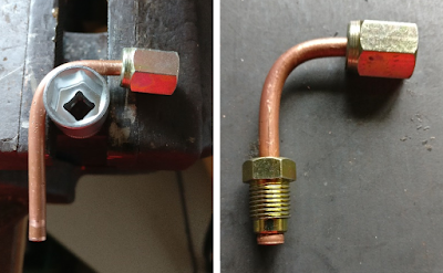
Offside front brake pipe.
The process of creating the near side brake line is very similar to the process for making the corresponding pipe at the rear e.g. create a pattern from garden wire and then transfer it in stages to the actual pipe.

The planned route for near side brake pipe.
Wire template of the route.
First bend on nearside front brake
Almost completed nearside front brake pipe
With the near side front brake pipe passing along the rear face of the front cross member, it then needs to be lined up with the front three-way union. By this point, I was getting pretty good at estimating angles and lengths.

Finalizing the length of the front nearside brake pipe.
The last step section of brake pipe to make goes from this front three-way union to the brake servo. This pipe is a little tricky to route due to the tight space and required bends. I finally settled on the route shown below.


With the brake lines completed, the next step is to finish off there mounting at the front of the chassis and secure the lines in place. That though is enough for this marathon entry!