Monday, September 30, 2019

Caliper Re-build

With the suspension almost complete, it's time to rebuild the calipers. Having already cleaned, de-rusted, and painted the calipers, it should be an easy task of installing new seals and giving the completed calipers a coat of shiny paint.

Front Caliper Rebuild

This ‘quick’ job starts with laying out all the tools (which I think are) need alongside the cleaned calipers. This includes the following
  • Plastic glue stick (a soft tool for prying inside the piston hosing)
  • 9 mm socket on ¾ inch wrench
  • Jamjar with dot 4 oil inside
  • Bike pump and old brake hose with an epoxied in football needle (made previously )
  • Wooden plank
  • Hammer (not really required… but a good practice to always have one handy)

Parts layout on my workbench.

I began by ensuring the caliper was still clean. Whilst I had given these parts a deep clean before, I felt another quick clean to remove any last particulates couldn’t hurt. For this, I removed the bleed nipple using the 9 mm socket and then sprayed plenty of brake cleaner through both this hole and the main brake line port. With the piston cavity wiped out and dry, the rebuilding can begin, starting with the seals. 


Front Caliper and piston ready for mating.
In the front caliper rebuild kit (part no. JLM12123) there are two seals which need to be re-installed (sketch of locations shown below). The first is a square edge O-ring, which acts as the primary oil seal between the pressurized brake system and the outside world, whilst allowing the piston to slide freely. The second is the dust seal, which prevents dirt and grime from getting onto the smooth piston surface which could damage the square edge seal.

Sketch of internal brake components.
The XJ40 build service manual suggests coating the square edge seal with plenty of dot 4 oil prior to installation. My low tech solution here was to drop the square edge seal into a small jar of dot 4 oil and leave for a for moments until it was required.

Square edge O ring in a jam jar of dot 4 oil.
This is then placed into the recessed region in the caliper. At first, the seal appears oversized for the recesses but with a plastic spatula, the seal easily slots into place. According to the manual, the key is to ensure the seal is not twisted and if it is, simply take it out and refit. I didn’t have 100% success each time, but it was easy to remove and repeat. 

Squared edged O-ring inside the caliper.
Now, this seal is in place the attention turns to the piston and the dust seal. This is a little trickier as one end of the dust seal fits into the outer recess on the caliper and the other fits into the lip on the piston. Following the procedure outlined in the Haynes manual, I didn’t find this too difficult (at least not compared to other jobs I’ve done so far).

This suggested procedure is as follows:
  • Using a finger apply a liberal coat of dot 4 oil onto the piston and inside the caliper.
  • Pass the dust seal over the piston in the correct orientation.
  • Ensure the end of the seal which fits into the piston is over the piston seal end. This was not a simple step, as due to the oiled surfaces, this seal easily slides off the piston!
  • Then place the base of the piston into the caliper. Ensure the bottom part of the seal sits in the correct recess within the caliper.
  • Using the plastic spatula slowly push in the remainder of the seal into the groove on the caliper. With gentle pushing and sliding the spatula around the edge, this easily slots into place.
  • The piston can then be pushed back into the caliper housing. Once the piston is all the way in, the top of the dust seal should automatically fit into the recess in the piston.
And with that, the first caliper is rebuilt. A stop motion video of this process is shown below.


To check the piston moved freely within the caliper, I connected each finished calipers to my bike pump using the modified brake line. To avoid the piston jumping out of the caliper due to the air pressure, I placed a thick piece of wood between the piston and the opposing edge of the caliper. Having rebuilt both front calipers, the pistons moved easily within the caliper. 

Rear Caliper Cockups

Having rebuilt the front calipers, I was ready to rinse and repeat the process on the rears. This was, however until I immediately realized that I had purchased the wrong replacement seals. No measuring was required a quick side by side comparison was all it took. Luckily I phone up SNG Barratt, explained my problem and they suggested that the correct part was JLM2200 and not JLM795. I posted back the wrong parts and they gave me a full refund, excellent service despite my cock up.

Smaller original parts next to the wrongly ordered larger new items!
The new seals arrived with the rear brake discs and shoes and hence why this blog post is appearing in this order. With the correct parts purchased the rebuild process was the same as that for the front. 

Correct rear caliper seal parts layout.

Dust seal on piston.

Dust seal and piston partially installed into the caliper.

Dust seal fully seated in the slot.

Finally assembled rear caliper.


Caliper Painting

Now the calipers are all rebuilt it's time to give them a shiny top coat of paint. I had been putting this off until they were rebuilt, as I didn’t want to run the risk of getting any spray paint into the piston housing. All the parts were given a quick scrub down with some sandpaper to give the surface a good key and then placed in a large box ready for painting, 

Blurry photo of brake parts waiting for sliver top coat.
In addition to the calipers, I also wanted to paint the caliper brackets as well to match. I brought a silver brake caliper paint off Amazon, which turned out to be a polish brand oddly enough. Despite this I was easily able to translate the instructions, that being shake well before spraying. To check the paint's colour and test for any reaction with the POR15, I initially just painted a caliper bracket.

Chosen caliper paint, and a before and after comparison of a caliper bracket.
I was happy with the result, so I decided to paint the rest of the calipers and brackets. Before painting the calipers I covered the piston and seals in masking tape. To stop paint getting into the caliper I refitted the old brake lines and bleed nipples. Several light coats later and the parts began to look very shiny! 

Freshly painted brake parts

Painted caliper and bracket.

The underside of the painted caliper.

Installing Rubber Sliders

The final stage of rebuilding the calipers is to install the rubber collars which the caliper pins slide in. The original collars from the donor car were in good condition and after a quick wash and brush up they came out like new. 

Caliper pin, rubber collars.
The recessed section fits into the caliper, either side of the piston. They are a tight fit and are held in place by the lip at the bottom of the collars. To aid installing these, a quick coat of Silicon grease was put on the recessed part.

Silicon grease applied to rubber collar.
With a little gentle teasing and pushing all these collars quickly fitted back into place. Since these are not going back on the car yet I have not got the slide pins out. That as they say is the plan for a different day. 

Fully painted and re-assembled rear brake caliper.

Sunday, June 9, 2019

Rear Suspension – Tie Bars

Before completing the final install of the rear end I wanted to trial fit the remaining components, that being the tie bars and the shock absorbers. Both these components and fitting hardware are supplied in the AK kit. 

Tie Bar Fitting

As with all AK parts these are supplied in bubble wrap for protection and come with two 7/16” x 3" + M12 washers and Nylocs nuts used to fasten the tie bar to the chassis. The first step is to fit the tie bars between the mounting points on the chassis and the differential tie bar bracket. Previous bloggers have warned about the poor fitment of these parts, be it due to the tie bar length or excessive powder coating preventing the ends of the tie bars fitting into the chassis. So I wonder what joys lye in store for me with this task. 

Tie bar and its fitting hardware. 
With a sense that a lot of potential tweaking might be about to happen, I began trying to fit the top part of the tie bar between the tabs welded onto the chassis. Straight away it was evident that the tie bar end was far too thick to fit between the mounting tabs. I, therefore, got out the hand fill and placed the tie bar in my bench vice. Whilst trying to keep the filled surface as flat as possible, I filled down both faces of the tie bar end. I also filled the inside surface of the tags welded on the chassis. After lots of trial fitting and filling, I eventually got the tie bar ends to fit into the mounting tabs. 

Filled down ends of the tie bar. 
After repeating this filling process on both tie bars I finally got them both to fit. I will return to these filled parts later and give them a coat of POR-15 to prevent them from rusting, but for now, I have bigger issues. 

The top part of tie bar fitted
With the tie bars fitted and temporarily secured to the top of the chassis, the next step is to check their fitment with the differential tie bar. With the tie bars rotated between the mounting tabs on the tie bar, the magnitude of my new problem becomes apparent. The through holes in the tie bar ends do not align with the corresponding holes on the tie bar bracket… bugger. Given one side appears low and the other two high, it looks like the differential/frame is rotated/twisted slightly. AK acknowledges that some miss aligned is expected and their suggestion is to drill out the holes to widen them, “Note due to some differences in Jaguar rear diff carriers it might need a drill running through before the bolts will line up.” This seems to go against all that I know about what tie bars are for and how they work, so I am keen to avoid this. I could go all ‘Project Binky’ on the frame cutting and re-welding it to level it off, but that seems excessive and beyond my skill set. 

The miss-alignment of the tie bars with the differential tie bar mount. 
A few simpler ideas came to mind about how to fix this including moving the tie bar mount and/or cutting the tie bar and welding collars over the bars to extend/shrink them. However, after discussing this further with Mark Gaby (a great sounding board with excellent ideas), the idea we came up with was to loosen the bolts which mount the differential to the chassis and then apply some gentle leverage to adjust the position of the differential such that the tie bar mounts line up. With this simple plan in mind, it’s time to see how it works. 

Nose bolts of differential loosened. 
With the differential, mount nuts loosened the next stage is to apply some gentle leverage to align the bracket and tie bar. I started by placing the trolley jack below the differential to raise the base of the differential, with no joy. I then got out my lady slipper and using the narrow tip was able to fit it through the bracket and just into the tie bar itself. With gentle leverage, I could just about align the two pieces. The problem that then arose was the lack of physical space, as with the holes aligned with the pry bar, I couldn’t then fit the bolts through that same hole. To make the matter more difficult I wasn’t able to pry from the other side or pass the bolt it from that side, so I needed another solution. To hold the two parts in their leveraged position with the lady slipper removed, I tried fitting a large no 10. Allen key into the aligned slot, from the tight backside. This was short enough to fit in this gap, whilst thick (wide) enough to keep the parts reasonable aligned. 

Applying leverage from the rear and then a large Allen key (on a socket) is slid in from the front to keep the parts temporally aligned. 
With the Allen key socket keeping the parts aligned the lady slipper could be removed and the greased bolts could slide through. This did require a few gentle taps with a hammer to get it through but it went in nicely. Having repeated this on one side the process was repeated on the other side to the same effect. 

Tie bar bolt partially installed.
Greased bolt being passed through the tie bar bracket and into the tie bar, whilst Allen key socket keeps the alignment from the other side.

Success! The bolt fits through the bracket and the tie bar end. 

One tie bar fitted!
Once both tie bars have been fitted its sadly time to pull it all apart so I can paint the filled faces of the tie bar and chassis tabs, to avoid them rusting. A few coats of POR15 later and the bars look as good as when they came from AK. As previously in this build all metal to metal contacts need a coating of copper grease and this includes both ends of the tie bar and the mounting taps for the on both the chassis and the tie bar bracket. 

(left) Re-painted tie bar ends (right) cooper greased ready for re-installation. 
The tie bars are then installed for the final time by repeating the above process the differential nuts are re-tightened. All this leveraging and nut tightening is certainly going to apply a static force/shear force to the differential which I assume will be taken up by the bushes. I suspect though that all this will impact my original measurements for the prop shaft shims… but that’s a problem for later (oh joy, more testing fitting of the prop shafts). 

Offering up the Shocks

The last remaining parts of the rear corner which I wanted to trial fit are the AK supplied shocks. Having read other blogs these seem to be an easy bolt on item. Let’s hope this is as true for my build. 

Shocks supplied by AK, still in their box 
The AK kit is supplied with all the required mount hardware, which is a pair of 7/16” x 4.5" and 7/16” x 2.5” bolts with corresponding Nylocs and M12 washers. Mixing metric and imperial here… something seems very off balanced to me. 

Shock with corresponding fitting hardware, also supplied by AK. 
Starting with the offside, the shock absorber is fitted first to the top mounting tabs, using the longer of the two bolts. The swing arm can then be raised and the shock absorber rotated outwards until the mounting holes line up. Then the shorter of the two bolts can be passed through a fastened in place. Both of these bolts fitted through the pre-drilled holes with no problem or miss alignment. At this stage, since I was just trial fitting I did not apply copper grease to these bolts and the nuts were only lightly tightened. 

Trial fitted shock absorber. 
Both sides went on easily, which was a welcome change from the tie bars. Once I was happy with the fitment they were then removed and placed back in their box for safe keeping. They have to be removed for the re-measurement of the chamber angle and final fitment of the rear hubs, but that will be the topic of another entry.

Wednesday, May 29, 2019

Rear Hub – Handbrake shoes

After test fitting the rear hub and prop shafts it is time again to place another order with SNG Barratt. This ordered includes the following
  • 1x Pair of rear discs (part number JLM1249)*
  • 1 x Pair of rear brake pads (part number JM1282)*
  • 1x Pair of handbrake shoes (part number JLM2209)
  • 4x Grub screws for discs (part number SF605047J)
  • 2 x Prop shaft nuts (part number JZN100035)
  • 14 x Shims (part number C16621)
  • 2 x rear brake caliper seals (part number JLM2200), as I ordered the wrong parts last time!
*update: the rear brake pads and discs are the wrong part number for a late XJ40 like mine, a problem I noticed later and have since resolved, but that is a cockup for a future post. 

Parts ordered from SNG Barratt. 

Let the Assembly Begin

With the new parts from SNG, the topic of this post if the final stage in rebuilding the rear hubs with their handbrake shoes. The new parts from SNG are only half of the parts I required for this stage, but after a quick rummage through my box of donor parts I found the remaining items; 
  • 2x painted splashed shields
  • 2x partially rebuilt hub carriers (with bearings and races)
  • 8x no. 8 Allen headed bolts and washers
  • 4x locking pins and corresponding springs
  • 4x hand brake retaining springs 
  • All components for 2 handbrake shoe adjusters 
  • 2x handbrake cables supplied by AK

Having found all the parts, I began as always with laying them out on the floor. 

Required components to rebuild rear handbrake.
I started with the two biggest items, the hub and the splash shield. The AK manual states that if the splash shield is damaged you can cut it down prior to fitting to the hub. You still require the inner circular section, as this holds the handbrake shoes to the hub, but the outer annulus is intended only to keep dirt and grit from the brake disc and so is not essential (especially for a relatively low mileage/good weather only kit car). Since  both of mine were in a decent condition I chose to leave them as a complete unit, as they will offer some protection. The one modification I did want to consider was a way of reducing the chance of corrosion between the shield and hub (a serious problem I found whilst cleaning these donor parts). To avoid water ingress into this area I decided to put a bead of RTV around the edge where the shield mounts to the hub carrier. The downside to this approach is that it will make it harder to remove the shield later if needed, and could also trap and keep water in this gap, if it gets in, which would make any corrosion worse. However, I decided to chance my arm that water would not get trapped in this gap and prevention was a better approach. 

RTV on hub carrier and the splash shield installed.

With a quick bead of RTV the splash shield was lowered over the hub and secured to the hub carrier by 4 no. 8 Allen headed bolts and washers (from the donor car). There was a considerable buildup of paint in these threads and so I had to run the bolts in, in stages which regular removal and cleaning of the threads. Finally, to ensure these bolt will not vibrate loose, I gave each of them a drop of locktight. 

The next step is to assemble the handbrake shoe adjuster. The cleaned adjuster (I know it doesn’t look it) is assembled from three components as shown below. Each mating surface is given a liberal coating of copper grease and rotated several times to ensure an even coating on all surface. The adjuster thread is then screwed fully into the cogged central piece before the cap placed over the top. This makes the assembling of the shoes and springer easier (or at least possible). 

Assembled adjuster.

Using the rebuilt adjuster and the pair of the springs I test assembled these with the new shoes. I did this away from the hub to make my first attempt as easy as possible as the springs are very strong and I didn’t want to scratch the fresh paint on the shield. 

As throughout this build, all metal-metal contact faces get a liberal coat of copper grease. This starts with the recesses in the shoe formers, where the adjuster and hand brake mechanisms slot into. However, the important thing to remember is that the copper grease should never touch any of the braking material and so careful application of the grease with just enough being applied is key. I know its common sense not to put grease on brake pad/shoes… but thought worth stating. 

Handbrake shoe with springs and adjuster. 

Having built up the first brake shoe the next step is to consider the handbrake mechanism. I was pleased to see that I still had the all-important small stud, which is used to secure the handbrake cable to this assembly. I was fearful of losing this and then struggling to find a new one. Before fitting this item, I ensured that all the metal to metal contact surfaces had a good coat of copper grease. This was certainly a messy job and the part required a good wipe down afterward. Despite this, the internal pieces certainly moved a lot smoother. I did leave some excess copper grease on the inside surfaces casing to avoid future ware. 

Handbrake mechanism with a light coat of copper, grease were required.

The last part of this assembly which needs to be trial fitted is the mounting of the hand brake cable. The recessed section on the rear of the hub was slightly too small for the mating surface on the handbrake cable. The solution was a small amount of filling on the handbrake cable matting surface to achieve the desired fit. 

Slightly filled down recessed lip on handbrake cable.
With this part prepared there is nothing left for it and its time to install the shoes onto the hub. The XJ40 build manual suggests applying small amounts of copper grease into the six contact points on the shield. My concern is not to apply to much grease and run the risk of this contaminating to the shoes. 

Brake shield with copper grease applied to high spots. 
With the shoes and springs assembled these are then placed over the central hub section and onto the splash shield. The next step is to fit the main handbrake mechanism. This starts by passing the handbrake cable up through the back of the hub carrier and through the tube in the splash shield. On the original donor car, there was a plastic retaining clip which I had kept, that sat between the shield and the hub carrier to keep this cable in place. However, this does not seem to fit onto the AK cable, and so can be discarded (Wish I hadn't spent 30 mins cleaning these two clips now). 

Handbrake cable being passed through hub and brake shield.
With the cable passed through the hub, the end of the cable can then be secured to the handbrake mechanism bypassing the small cylindrical stud through one arm of the mechanism and the end of the handbrake cable. This stud is retained in place solely by the overhang of the mechanisms outer casing, and so only work secured when in its 'normal' position. 

Partly assembled handbrake shoes
Each recessed end of the mechanism then gets a coating of copper grease, before slotting each end in turn into the corresponding cut out on the brake shoe. This is made a little easier by the fact the shoes can still lift up and rotate slightly, but is still a pig of a job to do thanks to the tension from the springs. 

With the handbrake cable and mechanism attached the final step is to add the hold-down pins to keep the pads on the splash shield. This is a simple job of placing each pin through a corresponding spring, then a hole in the shoes and finally the shield. These are then secured in place by pressing them down on the pin with a no. 5 Allen key and twisting to lock. Then the tension provided by the spring keeps the pin in place.

Assembled rear hub with handbrake shoes.
As someone who always wants to understand how and why things work, I must confess it took me a while to fully comprehend how the handbrake mechanism functions. So what I understand happens is when the cable is pulled, it pulls the inner section of the mechanism inboard towards the shield. Due to the arrangement of the pivot and the cable mounting location, as the cable is pulled, it has the effect of increasing the length of the mechanism, which in turn pushes the shoes out towards the drum. It also applies an outboard force (away from the shield) onto the shoes, which I guess is another reason for the pins/springs fitted in the last step. 

With the rear handbrake shoes fully assembled onto the hub, the last step is to pull the handbrake cable and check it all works. For that and a time-lapse look at the above build process, I have added the following video.... yeah video time!!!.


The process is then repeated to assemble the other hub. I must confess that despite the challenges of the springs, this is a rewarding job. I say this because afterward, you have two sub-assemblies which you can actually make do something! With these built the next step is to return to the chassis and continue with the rear suspension build. 

Tuesday, May 21, 2019

Rear Corner Build – Part 1

Having rebuilt the prop shafts and installed new races and bearings into the hub carries, it is now time for an initial fitment of the rear end. The plan here is firstly to check that all the parts go together, but also to get an idea of how many spacers/shims are required to achieve the desired chamber angle.

Installing the Re-built Hub

I chose to start by installing the rear hub carrier onto the swing arm using the donor lower fulcrum shaft. As is suggested in the manual, it is certainly worth trial fitting the fulcrum shaft through the swing arm by itself, to ensure it fits and there isn’t a significant buildup of powder coat. For these swing arms, it’s true to say the shafts are a tight fit but there is no real excess of paint. With a thin coat of copper grease on the shaft to ease the installation and later removal, the hub carrier was then installed to the swing arm. This job is a little cumbersome as you have to hold the hub at the correct position whilst sliding the shaft through. Gentle taps with a rubber mallet and the job is soon complete. 

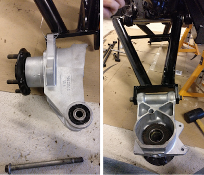
Installation of rear partly rebuilt hub onto the swing arm.

Installing the prop shaft

Next, the prop shaft is installed onto the differential. AK suggests that you begin by placing the donor prop shaft spacers between the prop shaft and differential. I can’t help but think this is a strange thing to assume as both the prop shaft and swing arm are new from AK, and so not sure how they can be sure these will be correct(ish). Since my original spacers were different sizes (6.4mm and 6.55mm thickness) I was extra careful to put them back on the correct side. These spacers slide over the bolts on the output of the diff. 

Donor spacers placed back on differential output flange.
The next step is to slide the prop shaft on and secure it in place with the 4 original 7/16" Unf Nyloc nuts. I decided here to add a washer between the nut and the prop shaft flange. The original nuts are used only during the trial fitting stage and will be replaced with new 7/16" Unf Nyloc nuts later when in final assembly. Whilst these nuts could be replaced with the somewhat more interesting Philidas nuts (part number NV607041#, which lead to an interesting morning read about these nuts), AK suggests the Nyloc nuts, so I’m sticking with their recommendation. 

Fitted prop shaft.
Fastening the nuts onto the prop shaft is a tricky process, as there is precious room between the opposing universal joint surfaces and unless you restrain the prop shaft, it will rotate as you tighten the nuts. After much trial and error, I found the easiest way to fastening each nut was it to rotate the prop shaft such that the 'target' nut was just off top center with the spline end of shaft resting on the floor. In this position, I could then use a 7/16’’ socket on a 100 mm extension to fasten the nuts. As you have to repeat this process for four bolts per side, this is certainly the least fun part of this job. 

Bring it all together

Now the splined end of the prop shaft can be passed through the respective rebuilt hub. To aid this, I slowly raised the hub/swing arm on the trolley jack whilst rotating and sliding in the splined end of the prop shaft. The tricky parts of this process are to protect the freshly painted hub carrier and getting the splined surfaces to line up. This is defiantly a cumbersome job where an extra hand would have been useful, but not essential. Once the prop shaft is slide into the hub, it is secured in place with a cone washer (smaller radius inboard) and a ‘special’ 1/16’’ nut (I found out why it is listed a 'special' in SNG manual later, no spoilers yet). Both these parts are taken from my donor car. The special nut is single use only, and so whilst I will use it for setting up the camber angle it will be replaced in final assembly. 

Prop shaft nut with cone spacer/washer.

With the hub installed onto the chassis for the first time, it is time to step back and admire the progress. If only I knew at that point that this would come apart so many more times. 

Hub fastened to prop shaft and swing arm. Resting on a trolley jack.
During my first attempt to fasten the special nut onto the chassis, I must have over tightened it (a good sign for later), as when I finally removed it, I noticed that inside the nut there is an inner coil/spring,  which is now unwinding itself from the nut. This must be another type of locking nut, and I guess what makes it ‘special’ and why it is single use…. 

Prop shaft nuts – over tightened.

Adjustment, Adjustments, Adjustments

With the rear corner assembled, the camber angle of the hub needs to be checked and altered. To do this, the top surface of the hub has to be 150 mm from the top of the chassis rail. This means careful raising of the hub on the trolley jack. I found the best way to measure the required distance was to use my father’s old set square, which luckily had a tongue length very close to 150 mm. I, therefore, placed the main surface on the chassis and raised the hub until it touched the set square. 

Set square used for checking the height. 
With the hub at the correct height, the aim is to ensure the (camber) angle hub is between 0 and 0.5 degrees (top of the slightly inboard) from the vertical. This angle of the hub is altered by changing the shims between the differential and the prop shaft. The concept being the thicker the shims, the more it pushes out the top of the hub. As with the front corner, I used an app on my phone to check the angle. For completeness, I used my spirit level, as, after all, I was going for near (or just off) vertical. 

On the off side, I found that with the original shim in place, the top of the hub was several degrees out beyond vertical. To resolve this, I took the entire assembly apart and reconstructed without the donor shim in place. This seemed to create almost the desired angle of 0.4deg.

The gap between the prop shaft and output flange

To verify the thickness of the desired spacer, again dismantled the corner and begun to fill it with 1 mm thick washers. The washers fitted nicely between the recessed region of the mounting plate and the bolts. I found these were a nice tool for experimenting with different shim thickness. Whilst I was not able to obtain the final shim thickness required, I was able to get a range of thickness in which I would find the desired angle. This should help determine how many shims I need to order from SNG. 

Differential output flange with washers to approximate the required shims.
Repeating the re-assembly process multiple times, with each time carefully checking the height of the hub, you can eventually get close to the correct angle.

Double checking the camber angle with a spirit level on the off side.

Final outcome

Having repeated this long process on both the off and near side, I ended up with an idea of what size shims I needed to purchase. 
  • offside required no additional shims for spacing
  • near side required between 5 mm and 6 mm of washers
Whilst I do not need any shims to get the correct camber angle, speaking with AK, they suggested filling the gap between the differential output plate and the prop shift with shims. I guess this is to spread the load onto the prop shaft, rather than relying on solely the pins. 

To achieve the required thickness on the near side, I might be able to get away with using the original donor shim. Whilst this might make things easy, I may consider buying some shims for this side so I have some flexibility when it comes to final fitment.

Now that I have an idea of what size shims I require there are several options to consider. 
  • Speed sensor rotor (CAC8713) which has a 1 mm thickness for £13.99. The actual speed sensor part is not required for the AK build.
  • A range of thicker spacers who’s part numbers are CBC4806xx, where the last two 'xx' are the thickness in mm, for example, the 5.5 mm spacer is part CBC480655. These parts varying costs but between £30 and £55, which are eye wateringly expensive for what they are.
  • Rear Camber Shim 0.020’’ (or approx. 0.5mm in useful units)  is part number C16621# and are 50p each.
Based on the prices and a recommendation from AK, I decided to go for the rear camber shims. So I added an order for 16 to my growing SNG basket. This order will also include the rear hand brake shoes, which will allow me to finish the assemble to the rear hubs prior to the final rebuild of the rear.