With the rear hubs (partially) rebuilt, the last step before these parts can be assembled onto the chassis is to assemble the half shafts. This starts with finding the AK supplied shortened half shafts as well as the separate splined and differential end plate pieces which came from my donor vehicle. The ends of the half shaft have been cleaned and painted. To assemble these separate parts into one complete shaft, I have to tackle the dreaded universal joints.
Spline Ends
The AK manual suggests you start with the splined end so my first task was to find these parts from amongst the cleaned and painted donor parts. Then I dug out the new universal Joints (UJ’s) from my large SNG suppled new parts box.
 |
| Splined half shaft end with new UJ. |
Since I had planned to follow the AK method of pressing the UJ caps in with a vice, my first step was to check if these parts would fit. So I opened the bench vice to its fullest extent (125 mm) and the splined end fitted in easily. With the vice open, it was simply a case of placing a UJ cap on one side and then closing the vice to press the cap into place. Once the cap is flush against the splined end, the vice can be opened and the part removed.
 |
| Vice pressing first UJ cap into the splined end of the half shaft. |
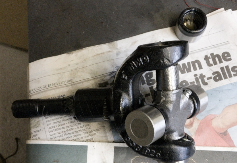
Now the UJ itself can be fitted to the splined end. To do this, remove the adjacent cap from the UJ and place this end into the empty side (the side without the cap) of the splined end. Once this end of the UJ is in place, the opposing side of the UJ should slide easily into the already installed cap. With the UJ pushed into the installed cap, the opposing cap can be installed using the vice/press method. Whilst doing this, be careful to ensure none of the needle bearings come lose or worse, fall out.
 |
| Initial fitment of the UJ into the splined end of the half shaft. |
Once this pair of caps are installed, the UJ can be rotated to ensure it moves somewhat freely. The final step for this pair of caps is to secure them in place with their respective circlips. To fit this, the caps need to sit below the surface of the splined end to expose the circlip grooves. This can be done by placing a set of small washers or a nut onto the cap surfaces and then placing back into the vice. Once the caps are sunken correctly, the new circlips are easy to insert.
I did find a few times that I had pushed one side of the caps in too far which meant I wasn’t able to install the opposing clips. This was easily remedied by placing the assembly back into the vice with a large nut placed on the lease recessed side and using the vice to press/shift the entire assembly through the splined end.
 |
| UJ fully installed in the splined end of the half shaft. |
With the UJ installed into the splined end, the process is then repeated to fit the splined end with the UJ into the main half shaft section. Again, start by installing one cap, followed by the UJ and then the opposing cap (almost sounds easy).
 |
| Time to repeat this process and install the opposing side of the UJ into the main half shaft. |
Differential output end
Once the splined end is attached to the main shaft section, the attention then turns to the separate, cleaned differential plate end. The installation of the UJ is the same as before, with the UJ initially being pressed into the smaller differential plate end. Then the differential end can be assembled to the original half shaft assembly.
 |
| Repeat the entire process on the differential mounting plate end. |
 |
| UJ installed into differential plate end. |
 |
| Final UJ cap (on this shafr) being pressed into place. |
Having assembled the first of the half shafts, the above steps are repeated to construct the other half shaft. I didn’t have too many difficulties with this process other than it being a very repetitive process, which required a surprising amount of effort.
 |
| One-half shaft assembled, now onto the next. |
Completed Parts
After just over a couple of hours’ work, both half shafts had been assembled.
 |
| Both half shafts fully assembled. |
Having rebuilt the last component of the rear suspension/drive system, the next step is to install all these parts on the chassis. Once these are installed onto the chassis I will then pump some grease into the UJ’s using the grease nipple.
Such a nice peice of information. Summed up all the things in a perfect way.
ReplyDeletegrease chassis