After test fitting the rear hub and prop shafts it is time again to place another order with SNG Barratt. This ordered includes the following
- 1x Pair of rear discs (part number JLM1249)*
- 1 x Pair of rear brake pads (part number JM1282)*
- 1x Pair of handbrake shoes (part number JLM2209)
- 4x Grub screws for discs (part number SF605047J)
- 2 x Prop shaft nuts (part number JZN100035)
- 14 x Shims (part number C16621)
- 2 x rear brake caliper seals (part number JLM2200), as I ordered the wrong parts last time!
*update: the rear brake pads and discs are the wrong part number for a late XJ40 like mine, a problem I noticed later and have since resolved, but that is a cockup for a future post.
 |
| Parts ordered from SNG Barratt. |
Let the Assembly Begin
With the new parts from SNG, the topic of this post if the final stage in rebuilding the rear hubs with their handbrake shoes. The new parts from SNG are only half of the parts I required for this stage, but after a quick rummage through my box of donor parts I found the remaining items;
- 2x painted splashed shields
- 2x partially rebuilt hub carriers (with bearings and races)
- 8x no. 8 Allen headed bolts and washers
- 4x locking pins and corresponding springs
- 4x hand brake retaining springs
- All components for 2 handbrake shoe adjusters
- 2x handbrake cables supplied by AK
Having found all the parts, I began as always with laying them out on the floor.
 |
| Required components to rebuild rear handbrake. |
I started with the two biggest items, the hub and the splash shield. The AK manual states that if the splash shield is damaged you can cut it down prior to fitting to the hub. You still require the inner circular section, as this holds the handbrake shoes to the hub, but the outer annulus is intended only to keep dirt and grit from the brake disc and so is not essential (especially for a relatively low mileage/good weather only kit car). Since both of mine were in a decent condition I chose to leave them as a complete unit, as they will offer some protection. The one modification I did want to consider was a way of reducing the chance of corrosion between the shield and hub (a serious problem I found whilst cleaning these donor parts). To avoid water ingress into this area I decided to put a bead of RTV around the edge where the shield mounts to the hub carrier. The downside to this approach is that it will make it harder to remove the shield later if needed, and could also trap and keep water in this gap, if it gets in, which would make any corrosion worse. However, I decided to chance my arm that water would not get trapped in this gap and prevention was a better approach.
 |
| RTV on hub carrier and the splash shield installed. |
With a quick bead of RTV the splash shield was lowered over the hub and secured to the hub carrier by 4 no. 8 Allen headed bolts and washers (from the donor car). There was a considerable buildup of paint in these threads and so I had to run the bolts in, in stages which regular removal and cleaning of the threads. Finally, to ensure these bolt will not vibrate loose, I gave each of them a drop of locktight.
The next step is to assemble the handbrake shoe adjuster. The cleaned adjuster (I know it doesn’t look it) is assembled from three components as shown below. Each mating surface is given a liberal coating of copper grease and rotated several times to ensure an even coating on all surface. The adjuster thread is then screwed fully into the cogged central piece before the cap placed over the top. This makes the assembling of the shoes and springer easier (or at least possible).
 |
| Assembled adjuster. |
Using the rebuilt adjuster and the pair of the springs I test assembled these with the new shoes. I did this away from the hub to make my first attempt as easy as possible as the springs are very strong and I didn’t want to scratch the fresh paint on the shield.
As throughout this build, all metal-metal contact faces get a liberal coat of copper grease. This starts with the recesses in the shoe formers, where the adjuster and hand brake mechanisms slot into. However, the important thing to remember is that the copper grease should never touch any of the braking material and so careful application of the grease with just enough being applied is key. I know its common sense not to put grease on brake pad/shoes… but thought worth stating.
 |
| Handbrake shoe with springs and adjuster. |
Having built up the first brake shoe the next step is to consider the handbrake mechanism. I was pleased to see that I still had the all-important small stud, which is used to secure the handbrake cable to this assembly. I was fearful of losing this and then struggling to find a new one. Before fitting this item, I ensured that all the metal to metal contact surfaces had a good coat of copper grease. This was certainly a messy job and the part required a good wipe down afterward. Despite this, the internal pieces certainly moved a lot smoother. I did leave some excess copper grease on the inside surfaces casing to avoid future ware.
 |
| Handbrake mechanism with a light coat of copper, grease were required. |
The last part of this assembly which needs to be trial fitted is the mounting of the hand brake cable. The recessed section on the rear of the hub was slightly too small for the mating surface on the handbrake cable. The solution was a small amount of filling on the handbrake cable matting surface to achieve the desired fit.
 |
| Slightly filled down recessed lip on handbrake cable. |
With this part prepared there is nothing left for it and its time to install the shoes onto the hub. The XJ40 build manual suggests applying small amounts of copper grease into the six contact points on the shield. My concern is not to apply to much grease and run the risk of this contaminating to the shoes.
 |
| Brake shield with copper grease applied to high spots. |
With the shoes and springs assembled these are then placed over the central hub section and onto the splash shield. The next step is to fit the main handbrake mechanism. This starts by passing the handbrake cable up through the back of the hub carrier and through the tube in the splash shield. On the original donor car, there was a plastic retaining clip which I had kept, that sat between the shield and the hub carrier to keep this cable in place. However, this does not seem to fit onto the AK cable, and so can be discarded (Wish I hadn't spent 30 mins cleaning these two clips now).
 |
| Handbrake cable being passed through hub and brake shield. |
With the cable passed through the hub, the end of the cable can then be secured to the handbrake mechanism bypassing the small cylindrical stud through one arm of the mechanism and the end of the handbrake cable. This stud is retained in place solely by the overhang of the mechanisms outer casing, and so only work secured when in its 'normal' position.
 |
| Partly assembled handbrake shoes |
Each recessed end of the mechanism then gets a coating of copper grease, before slotting each end in turn into the corresponding cut out on the brake shoe. This is made a little easier by the fact the shoes can still lift up and rotate slightly, but is still a pig of a job to do thanks to the tension from the springs.
With the handbrake cable and mechanism attached the final step is to add the hold-down pins to keep the pads on the splash shield. This is a simple job of placing each pin through a corresponding spring, then a hole in the shoes and finally the shield. These are then secured in place by pressing them down on the pin with a no. 5 Allen key and twisting to lock. Then the tension provided by the spring keeps the pin in place.
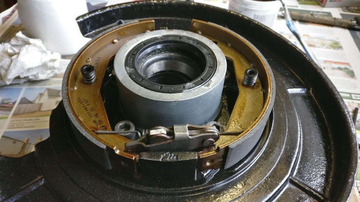 |
| Assembled rear hub with handbrake shoes. |
As someone who always wants to understand how and why things work, I must confess it took me a while to fully comprehend how the handbrake mechanism functions. So what I understand happens is when the cable is pulled, it pulls the inner section of the mechanism inboard towards the shield. Due to the arrangement of the pivot and the cable mounting location, as the cable is pulled, it has the effect of increasing the length of the mechanism, which in turn pushes the shoes out towards the drum. It also applies an outboard force (away from the shield) onto the shoes, which I guess is another reason for the pins/springs fitted in the last step.
With the rear handbrake shoes fully assembled onto the hub, the last step is to pull the handbrake cable and check it all works. For that and a time-lapse look at the above build process, I have added the following video.... yeah video time!!!.
The process is then repeated to assemble the other hub. I must confess that despite the challenges of the springs, this is a rewarding job. I say this because afterward, you have two sub-assemblies which you can actually make do something! With these built the next step is to return to the chassis and continue with the rear suspension build.
No comments:
Post a Comment